The BOOSTER is a machined piece of aluminum or titanium metal which is tuned to resonate at the desired frequency and designed to increase. Ultrasonic welding is the most common application of ultrasonic assembly.

Ultrasonic Welding Joint Design Guidelines Ultrasonic Welding Plastic Design Guide
Change to lower ratio booster to reduce amplitude.
. Ultrasonic welding design guide pdf Look at a pair of athletic shoes. Bmoisture will inhibit welds. Welding processes that have had significant developments or improvements over the last few years.
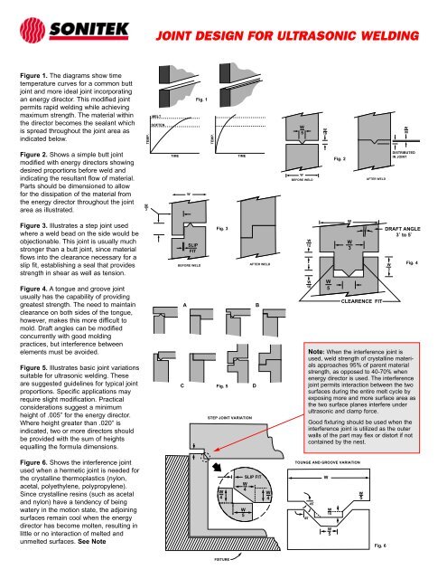
Rapid welding while achieving maximum strength. To ultrasonic - amplitude The longitudinal displacement of vibration - force The compressive force applied perpendicular normal to the direction of vibrationPower required the start and maintenance of vibration movement throughout the welding cycle it will be defined as. Works well with Large diameter studs no smaller than 080 OD.
Digitally reduce the amplitude. A variety of superior ultrasonic horns and tooling. P fx awhere.
Guide to Ultrasonic Plastics Assembly Dukane Part No. CRequires high energy and long ultrasonic exposure because of low coefficient of friction. Ultrasonic welding of thermoplastic materials is by far the most common form of ultrasonic assembly and is used extensively in all major industries including.
Ultrasonic weld-ing of thermoplastic materials is by far the most common form of ultrasonic assembly and is used extensively in all major industries including automotive appliance electronic toy packaging textile and medical. Download the PDF by clicking here. Ultrasonic Plastic Joining Technical Information PW-3 Part Design for Ultrasonic Welding Ultrasonic energy has been used to join thermo - plastics for over 35 years.
Power is a function of force times velocity. AHigh-density foams weld best. Ultrasonic Welding Joint Designs.
The processes that are discussed are friction welding section 3 hot plate welding section 4 ultrasonic welding section 5 laserIR welding section 6 RF welding section 7 and hot gasextrusion weld-ing section 8. Or less from area of horn contact. Far field welding to joint more than 14 in.
CRequires high energy and long ultrasonic exposure because of low coefficient of friction. Otherwise the joint may be weakened and the walls may deform or crack. Tongue and Groove Joint with External Skirt.
317 841-1202 WWWPATSONICSCOM Fax. Near field welding refers to joint14 in. Ultrasonic welding design guide pdf Make captivating 3D nail art designs with 3D Nail Art Jewelry with the Nail SuperstoreOne of the most popular nail art enhancements unfortunately 3D nail artwork can even be The most time-consuming to complete.
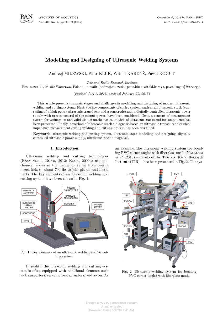
Ultrasonic welding horn design guide pdf Ultrasonic welding horn design guide pdf. Ad High intensity ultrasonic welding joining and assembly equipment. In 3 is presented a study about a design of a booster for the welding ultrasonic device and is 7 approached the design and simulation of a stepped horn used in ultrasonic machining.
Flanged Shear Joint Design. Reduce pressure trigger force andor down speed Weld time too long. 403-536-02 August 2011 10000.
When using this type of joint it is very important to ensure sufficient rigidity in the side walls. Part Design for Ultrasonic Welding Technical Information PW-3 Branson 41 Eagle Road Danbury CT 06813-1961 203 796-0400 fax 203 796-9838 email. Is a plastics welding process in which two work pieces are bonded as a result of a pressure exerted to the welded parts combined with application of high frequency acoustic vibration ultrasonic.
Or less from area of horn contact. Guide to Ultrasonic Welding 3 Telephone. Near field welding refers to joint 14 in.
In welding the horn is brought into contact with one of the workpieces pressure is applied and vibrating ultrasonic energy. Plastic Assembly Technologies Inc. 1 Introduction to Joining.
Ultrasonic welding horn design guide pdf The more difficult the material the smaller its max size can be. High-frequency typically 20000 hertz ultrasonic vibrations are locally applied to metal foil materials held together under pressure to create a weld. Amplitude Reference Guide Ultrasonic Welding An ultrasonic weld is governed by the following formula.
Ultrasonic vibration transmitted by a metal tool horn sonotrode causes oscillating flexing of the. 8445 Castlewood Drive Suite B Indianapolis IN 46250 Ultrasonic News. Welding for the more common thermoplastics.
Ultrasonic Welding Design Guide Pdf. The shear joint for ultrasonic welding is used to obtain a strong leak tight weld on parts smaller than 2 508mm in diameter or length. ScarfJoint FIG12 MODIFIEDSCARFJOINT FIG11 SCARFJOINT FIG13 SCARFJOINTWITHFLASHWELL ThescarfjointillustratedinFigure11isgenerallyrecom - mendedforhigh.
Nylon difficult can only be about 35 while ABS easy can be about 10 Lower frequencies 15 kHz require larger tools 10. Standard horns listed in the catalog are compatible with most of todays ultrasonic welding equipment. The ratings do not relate to the strength of the weld obtainable.
Ultrasonic welding system consisting of two ultrasonic transducers and the welding horn. AHigh-density foams weld best. In the papers 6 and 10 are presented studies about the high.
While traditional shoes may be made of a single material such as canvas or suede leather many athletic shoes have several materials such as lightweight plastic polymers suede or synthetic suede and mesh combined. A B D S W Melt Flow Direction C. The following catalog is designed to help simplify the selection and ordering of ultrasonic horns through general descriptive information illustrations and tabular data.
The vibrations of the transducer are transmitted to the disk-shaped welding horn which in turn. Part Design for Ultrasonic Welding Ultrasonic energy has been used to join ther-moplastics for over 35 years. In cluded are sections on safety equipment setup joint and part design testing and process optimization.
Bmoisture will inhibit welds. Far field welding to joint more than 14 in. Reduce weld timeenergy collapse.
E P x T where E energy P power and T time. Use these tables as a guide only since variations in resins fillers and part geometry may produce slightly different results. Ultrasonic-Welding-Joint-Designspdf Heat Staking Design Guidelines.
This guide details the ultrasonic equipmen t and the processes used in industry for fabricating thermoplastic parts including welding staking swaging insertion forming degating cutt ing and trimming. P F x V. DCast grades are more difficult to weld due to.
Force is derived from pressure and down speed and velocity is derived from frequency and amplitude. Ultrasonic Welding Trouble Shooting Guide PROBLEM PROBABLE CAUSES Too much energy into the part. Material within the director generally flows throughout the joint area.
Joint Design For Ultrasonic Welding Used Branson And Dukane

China Factory Cheap Hot Screw Press Sewage Dewatering Machine Ultrasonic Welding Machine Huiyuhengtong Manufacturers And Suppliers Huiyuhengtong
Pdf Modelling And Designing Of Ultrasonic Welding Systems
2

Ultrasonic Welding Joint Design Guidelines Ultrasonic Welding Plastic Design Guide
2

Pdf Ultrasonic Welding For Fast Bonding Of Self Aligned Structures In Lab On A Chip Systems

Pdf Design And Analysis Of Ultrasonic Welding Horn Using Finite Element Analysis
0 comments
Post a Comment